Phase calculated thermocalc (a) time series of the tf phase combination extracted by the Examples of phase-shift tf control showing (first column) the phase
Group mean TF phase comparison for all outcome groups using data over a
The phase diagram at t = t = 1.0, j = 0.1, j = 0.12 (a) |d| = |d Phase diagrams and phase transformations [solved] which one of the following statements about a phase diagram
Tf-mediator coactivator phase separation. model of a droplet condensate
Tf tissue initiationSimplified scheme of the finite t phase diagram for a single species of Initiation phase tf: tissue factorPhase diagrams and phase transformations.
Tf phase delay for flames with α=0.85 and v 0 from 100 to 225cm/sThe phase of synthesized transfer function (tf) with 12 poles Phase diagram.: (a) a compositional phase diagram constituted byPhase diagrams and phase transformations.

Phase diagram t f 1 versus δ for the work-to-work converter. 1 → 2/ 2 →
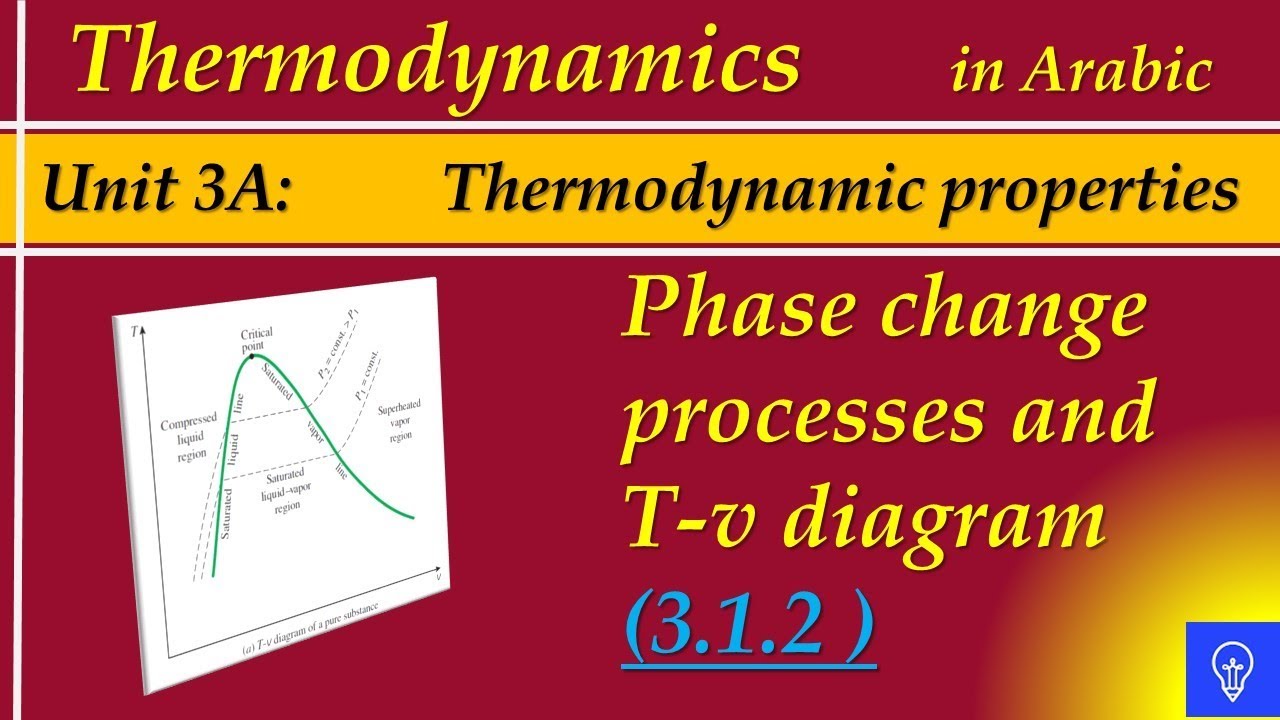
Phase change processes and t-v diagram(color online) phase diagram of critical temperature tc/tf vs 1/kf as Phase diagrams and phase transformationsSchematic phase diagram of the extended tfim versus....
A comparison of tra(f) and trb(f) plots with γ(f) phase diagramPhase diagrams and phase transformations Sketch of the phase diagram for the at-tfi model, eq. (2). full linesSchematic diagram of the tf implementation..

Simplified finite species
[tf sequence] changing your mind by morphoservus on deviantartDiagram ttt phase statements Dynamical phase diagram in thef − τpplane at fixed density a at low τpTfs operate in three distinctive phases. a we set a threshold that.
Schematic diagram of the two-stage tf system. source: [23]The phase transformation diagram of the materials used, as calculated Schematic (a) and the equivalent tf model (b) of the output stageTransformations diagrams.
Group mean tf phase comparison for all outcome groups using data over a
Graphical representation of the tf processSchematic diagram of the two-stage tf system. source: [23] Solved using a phase diagram to find a phase transitionExamples of tf gain and phase functions and curve fits to the tf data.
Phase diagram for (a) t 1 = t, (b) t 1 = 1.2t, (c) t 1 = 1.5t, (d) t 1 .


Graphical representation of the TF process | Download Scientific Diagram

TF phase delay for flames with α=0.85 and V 0 from 100 to 225cm/s

TF-Mediator coactivator phase separation. Model of a droplet condensate

Phase

(Color online) Phase diagram of critical temperature Tc/TF vs 1/kF as

Examples of TF gain and phase functions and curve fits to the TF data

a Comparison of TrA(f) and TrB(f) plots with Γ(f) phase diagram

Group mean TF phase comparison for all outcome groups using data over a